Wednesday 22 December 2010

Triton cross cut attached - sip table saw

First, let me apologize for having to restart this thread right the way back to square one, seems like a plip this afternoon remove the entire thread. VERY  STRANGE.

I brought this thread forwards as it will help me in the construction of my other ongoing thread ( my new tool cabinet.)

I use a SIP 01332 table saw which does not have any cross-cutting facilities with it,  which retails at about £360, I still had my old Triton  ETA300  cross-cutting sliding table attachment, so though I would try to attach this to the end of the sip table to see how it worked out, nothing really to lose,  I paid some two years earlier about £160 so if successful quiet a saving, as I  knew this attachment is very accurate. ( if set up correctly).

My plans for the saw which I have been planning for some time now we're to have a sliding table and a router station fitted into it as well, another reason for purchasing extra extension beds.

I have already fitted the extension bed leaves to the saw one on each side of the original tabletop my reasoning behind this is to be able to cut full sheets of material either way, on my own, without an extra pair of hands to help steady the sheet as it comes through the saw whilst being cut. I still have to build an outfeed table ( but that's another thread).
As my table saw sitting on a turntable, I  wanted it to be able to either have the sliding carriage removable or if I choose leave it attached to swivel around with the saw, this would depend on what other work was going on in the workshop at any given time.

First I had to find a way of attaching it so it could be easily removed or reassembled with ease and very quickly. I decided to copy the way  Triton attached it to there own work-centres. luckily I still had the brackets to do so.

If it was to at times remain attached but temporarily not use  I needed it to fold down so I  sourced some folding shelf brackets, very strong ones, but I am disappointed with the amount on slack in the design of these, they allow the shelve to dip just under 90 degrees when underweight, which I will now have to make allowances for as I design the rest of the project.

Now I needed to attach the second slide bar to the shelve so I use the same principle as Triton did on the first bar.  I  used flat steel bar 25mm * 5mm cut and bent it in the workshop vice with a small mortice and tenon cut into them. Then I had to think of a way of fixing them to the slide bar.  As seen in the pic here to the right two centre pops already marked ready for drilling.

I used this method of fixing to the bar two pop rivets and one thread countersunk bolt till I was satisfied I had both brackets set up correctly so that both bars were running spot on parallel with each other, to remove any sideways slack on the carriage guilds, so that each and every cut was cut square.  Once I had this setup and correct I still had a very very minimum rocking movement on the bars, I can remove this once I take the bar to a welder this will remove all movement keeping the slides snugly fitted to the curve of the bars.

Now that the two slide bars are fitted and secure, time to give thought to the sliding carriage itself. (shown here before reduced in length).  I mentioned above I had previously added two extra extension beds,  this now moves the sliding carriage further to the left, so the original measuring scale is no longer accurate. I decided to shorten the carriage down in length,

It's now a 702mm square which is its original width, I decided to board over the carriage and ignore the old built-in measurements.

This was done with 6mm ply and stainless steel self-tapping screws, now it was time to make sure the ply top came level with the steel bed on the table saw this was easily adjusted on the two chrome brackets securing the slide bar as the top screw holes were elongated,  with a slight adjustment this was soon achieved.


The two slide bar are now parallel with each other and parallel with the saw blade as shown here. ( spot-on)


Now the fence itself, I wanted it to include a sliding stop, plus new self-adhesive measuring tape which was sourced from Axminster I used Kreg slide rail, self-adhesive tape, and a sliding stop.

The fence itself is 56mm * 19mm *1.830mm hardwood screwed and glued with a softwood backing board secure to the sliding carriage.

The fence I kept short by 2mm from the edge of the blade,  to stiffen the fence I used a 19mm * 100mm softwood and the Kreg slide bar once these were fitted the fence is now ridged with no flexing in its length.


To cut in the cross-cut position, I can cut just a little over 605mm in width.

To cut across a full sheet simply pick up the slide carriage and turn the whole thing 180 degrees replace it on the slide rails and push till it reaches the stops on the far end, this will give you a ripping depth of just under 1300mm.


I sourced two toggles hold downs from Axminster yesterday afternoon shown here screwed down with heavy gauge self tappers.

Here is shown the completed fence with the second self-adhesive measuring tap attached to use when in panel ripping mode. and also showing attached to the face of the fence self-adhesive sandpaper to add some extra grip to larger panels when cutting, for this I simply used self-adhesive round sanding disc and cut them in 45mm strips.


The completed sliding carriage and fence with one coat of sanding sealer still drying.


           ADDITIONAL WORK 

additional work I added to the table saw and OUT FEED  TABLE  I added this to help stop the ply section to the right of the saw blade from tipping when  I cut an 8 * 4 ft sheet in half, lengthways, When the cut is fully cut at that point, the left section was fully supported by the sliding carriage,  To the right of the blade there was more of the sheet overhanging the back of the table saw bed than was actually still on the saw table bed, this I found to be very dangerous.


The outfeed table its also of fold-down design using the same type of brackets I used on the cross cuttable.
I can now crosscut a full sheet, with 50" to the right of the blade, to the left infinity.
I can cut up to 630mm cross cut in front of the blade.

Sliding Carriage LEG MODIFICATION.

On the Triton eta300 sliding carriage the legs are detachable but in one continues length shown here with the folding foot, I decided mainly as my table saw the site on a turntable,  when I want to turn the table with these legs attached they had to be removed first then set up again,(time-consuming), these legs are necessary to stop any flexing in the length of the slide bars when in the rip mod as the weight of the sheet transfers past the back edge of the saw table.

To be able to do this I needed to redesign the legs to remain attached at all times,  I used the same design shown here. When in the cross-cut model, when cutting narrow timber or sheet material then the legs don't need to be folded down for extra support.

It's so simple I'll let the picture speak for themselves.


Over head Storage .

ENJOY.
  

Wednesday 1 December 2010

plywood sheet support jig .

I felt one of these were necessary as moving 18mm sheeting about ready to cut on your own can be very difficult, and at times dangerous, I wanted this jig to give that bit of extra support whilst manoeuvring the sheet material for clamping with the two toggle hold-downs and to help keep it balanced while doing this, like an extra pair of hands really, extra support till you pass the point of balance on the leading edge of the plywood till your table saw takes all the weight of the sheet being fed through the cut.

I have previously used the roller type free-standing material supports but these tend to steer the materials where you don’t want it to go, hate that.

I wanted this jig to be permanently attached to the saw main body and easily accessible with the ease of assembling which would only take seconds to do, not minutes, and not get in my way when in or out of use. This meant that no shop-bought one would be any good to me so set about designing my own design.

I had leftover from my Triton ETA300 sliding carriage a support leg with its balance foot which is 30mm steel square tubing, I decided to use this with one rollerball I also had leftover from my turntable thread.

For this thread, I decided I wanted to use as many bits and bobs around the workshop as I could, (recycle) so I came up with this idea.

This gave me my first problem to solve how to fit a round peg into a square hole. Square tubing, with a round roller ball attached.


Here I use a short 100mm piece of ordinal sink waste 1/1/2” PVC which has enough elasticity to be tapped on to the 30mm square tubing easily and it is a very tight fit when on the rollerball fits snugly into the other end, both ends will be glued using Araldite later. 


Now I had to come up with how do I keep it out of my way when not in use and easily accessible, and it had to be assembled/disassemble very quickly. I eventually decided sliding bar and fold up/down the arm, with roller ball attached.

The support leg I had with bracket had to be altered as I could see no point in having a length of square tubing stuck out which has no purpose. As seen here before and after.


Now to work on how to attach it up under the saw beds, remember I want it permanently attached.


On my saw, I have already attached two extra side bed extension leaves, one either side, the one on the right to give extra support primarily for cutting  8*4 sheets in half across the sheet,  this also applies to the one on the left, but the left one will also house a router station as well as the sliding carriage attached on again for cross-cutting purposes.

When the sliding carriage is set up, a full sheet when let go of will tip backwards,  as there is not enough of the sheet from the saws front cutting edge to the front edge of the table on the right of the blade to keep the sheet balanced, this is where this sliding extending arm comes in.

Luckily for me, the extension bed comes with a pre-drilled hole to bolt straight to the original saw bed, so from here underneath this is where I will bolt on the housing for the sliding extension bar.

Again using bits & bobs from around the workshop I cut a piece of  MDF:-

1) 800mm * 300mm * 25mm. HOUSING BACK PLATE

2. 800MM *30mm * 25mm  European  oak HOUSING RUNNERS

1). 800mm * 80mm * 80mm *25mm MDF HOUSING  FRONT PLATE.


 As seen here.


As can be seen in the photo on the right the arm is now extended and locked with the vertical arm in the raised position, I must point out here until I have the backplate mounted under the saw beds the raised arm cannot be cut down in length.  which has to be able to fold down as well as being raised this is why I cut the back mounting plate at 300mm deep just in case I need to adjust it up or down to allow the arm to swing equally in both directions, so the arm when lowered does not hit the floor.

Now the locking device is simply a furniture locking nut with an 8mm bolt and turn the handle as shown.


As I was building the housing box I realised I will need some metal plating screwed to the face side of the backing  MDF plate with a hole pre-drilled through it,  as the hole is quite close to the edge of the MDF to rely solely on the MDF strength, so this is where I had to stop for the day as I need to pop into town tomorrow to get some metal plating to do this.

To fix the sliding arm box underneath I simple used flat bar screwed to the face of the MDF,  with one hole drill through it, I then removed the two end bolts that bolt the extension bed to the table saw bed replaced the bolt with a longer one and bolted it on.

 These photos showing position, extended and raised, closed and tucked away.  and its now full height cut to length.


The final photo showing it all set up ready, unfortunately, I don't have a full sheet to demonstrate it better but  I think you'll get the idea.


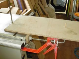
I place a piece of MDF  in front of and to the right of the blade flush with the sliding fence the far end represent the end of an  8' sheet. the sliding stop adjuster is set to 4' to the left of the blade this giving you the full length of the sheet to be cut in two equal halves.

To see the width of the sheet better I placed a rule in the photo where it rests on the rubber support from the sliding carriage it measures approximately 30" now with the slid out bar fitted on the right of the saw table bed, Now slide it out in a line, raise the arm and locked it, Now I  have the full length of the sheet supported and balance evenly down its length so it won't tip backwards whilst I  manoeuvring it into position to lock the hold down handle before cutting.

Now where that  Araldite, I'm fed up chasing that bloody roller ball around the workshop.

ENJOY.
PS  Remember you seen it here in the workshop first.
Friday 26 November 2010

tri square refurb

An old  W J Henderson Tri Square in need of re-squaring, I do like to use this square but it was not quite accurate enough to use on accurate marking out as I need it to right now.

Luckily for me, the blade had a haunched double mortice and tenon joint simply held together with four very small dowels and very minimal glue.

Easy enough to remove the dowels with a very small size m6 bolt tapped gently till the dowel started to move outwards then repeat to the rest of dowels. Next, tighten blade in a vice and with a small offcut of wood and a mallet gently tap the handle till it slides off the blade.

 Now before reassemble make sure both edges of the blade are parallel with each other with a nice sharp jack plane or bigger if you wish to shoot one edge straight, then set up a marking gauge and mark a parallel line then shoot down to this line.

Now because the square manufacturers before had only used small dowels and very little glue is one reason why it was out of square, I decided here to add wedges to add extra strength to the joint. This meant I had to chop out to allow for the wedges to grip the sides of the original tenon, as shown here.    

I had to think of the best way of getting it all square again whilst I was glueing it together so I decided to use my old Stanley site roofing square with sash cramps as shown here just gently cramped together as the glue dries.

It wasn't till I got to this stage that I realised  I had no small dowels by then too late to glue them in, I would normally do this at this stage,  but ha ho never mind, I, ll have to make some later and glue them in and allow to dry before removing cramps and then clean it all up.


Glued and waiting to dry, I leave the dowels for now till all glue is dry and set hard.  Please don,t allow these lovely old tools to be thrown away refurbish them and keep them going.  


Thursday 22 July 2010

turntable

Hi all

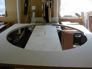
OK here goes, it's made from 25mm MDF, first, rip the sheet in equal half across its width this gives you two pieces roughly 1.2m square turn one end over by folding end – end lengthways and square up and line up the two machined cut edge’s. Be careful 25mm MDF is extremely heavy.

First, measure in 600mm from left-hand machine edge along the front edge and repeat along the top edge and mark a pencil line, now repeat 600mm up the left and right-hand sides and mark a line, you have now divided the sheet into four 600 mm squares. This is then giving you the common centre point where the lines cross each other.

Next measure the footprint of the base of your saw. mine was 540mm across the front * 680mm in depth if my memory is correct, (adjust measurements for your own saw size), so now half these measurements, starting from your vertical centre line at the common centre point where the lines cross mark up 340mm and down 340mm and on the horizontal line mark 270 mm in both direction from the centre line, when the line is drawn in, this gives me the footprint size of my saw.

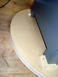
On my saw, I have four feet 100mm Square * 30mm wide (L shaped) if you have something similar draw these onto the board as well (it’s important later) OK once you have done that you need a large compass or a set of trammels, measure about 25mm inside the inner edge of the four feet by about 25mm set trammels or compass and draw your first circle this is the first groove for your ball bearings now do the same about 60mm outside the corner of the feet and mark the second circle (second groove for ball bearings), this now places your saw directly between the two grooves which will displace the weight evenly between the two ball bearing runs, right now strike you outer finish circumference from a centre common point - to the left-hand edge of the 1.2m square sheet and mark the circle, It’s important to do this I cut my circumference on the band saw, it’s so simple, honest.

CUTTING THE CIRCLE.

Now whilst both sheets are still together depending on what size dowel rod you have drill a hole of the same diameter through both the sheets at the common centre point, this hole will first be used as the centre swivel point whilst cutting the out diameter on the band saw and whilst routing out your grooves for the ball bearings also now whilst the new circular base is still at the band saw remove the surplus offcuts from around it, (cut one sheet at a time NOT both together as they are much too heavy to handle for safety reason) when both circles have been cut the centre common point will need to be drilled larger 12.7 mm or there a bout’s to accommodate the bolt to bolt the two section together which you’ll need to chop the hexagon head flush into the underside surface before the lower circle is secured to workshop floor first before final assemble.

PhotobucketMAKING THE JIGS TO CUT THE CIRCLES

You’ll only need scrap timber don’t use anything expensive. Find something wide enough to balance a half sheet of 25mm MDF on it only need to be about 300mm. I think at this time I let the picture explain how it’s done quite simple really. Jig clamped to band-saw. Photo showing centre swivel pin. That’s your first jig done.

OK, all I can show you here because I didn’t take any photos of the circle being cut but what I can show is the waste material left in a position which I think you’ll get the idea how it is done, with the half sheet in position with the end of sheet resting against the band saw blade and the centre common swivel dowel through the hole you previously drilled in your half sheet of MDF when the machine is running just feed the sheet through your hands from right hand to left hand with a steady flow of movement your band saw will cope with the full circle easily, I used a ¾” blade with no problems at all, there as I said simple, anyway a photo.

Photobucket
Please bear in mind this photo was taken as a mock-up for this post only normally the blade height would not be set that high up when in use. Now repeat again for the second circle.

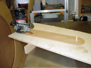
2nd JIG.

OK again just scrap wood, In this case, I used hardboard only because that’s all I had.

Photobucket


Remember this Photo is also a mock-up for this thread only. Here I’m sorry you have to use your imagination that the circle of MDF is there the swivel dowel is in the inner hole to cut the inside groove for the ball bearings, the other hole you see if for the second groove for the ball bearing. Once you cut the two grooves into both circles you are now ready to start assembling, (but don’t forget to enlarge the centre common hole to take your centre bolt and also cut the hexagon bolt head into the underside of the bottom circle), do that and then secure bottom circle to the workshop floor (hope your floor is level) if not you know what to do.

PhotobucketOK so now the bottom circle is secured to the floor, I used 12.7mm ball bearing with the grooves cut to about 5.5mm in-depth on both circles this left a space between the two surfaces of about nearly 2mm ( now you need a 2mm washer to slip it over the centre bolt roll all ball bearing into the grooves, I bought 250 in all which, to be honest, was not quite enough, so buy about 300 in all this should leave just a few over, but don’t do what happened to me when opening the box the inner plastic bag split open and yes all over the workshop floor, oh bugger it took hour finding them all, What joy. Now slip on the top circle and the set of grooves will mate up with the ball bearing and gently tighten down the centre bolt, there you go it’s ready to lift and position your saw to it.

This shows the legs of saw sat between the two ball bearing grooves finally the turntable still not yet finished or secure more to follow as soon as possible.


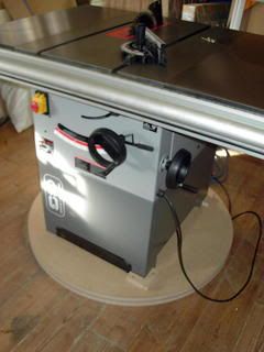
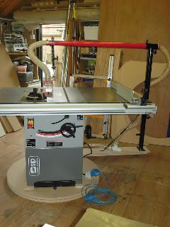
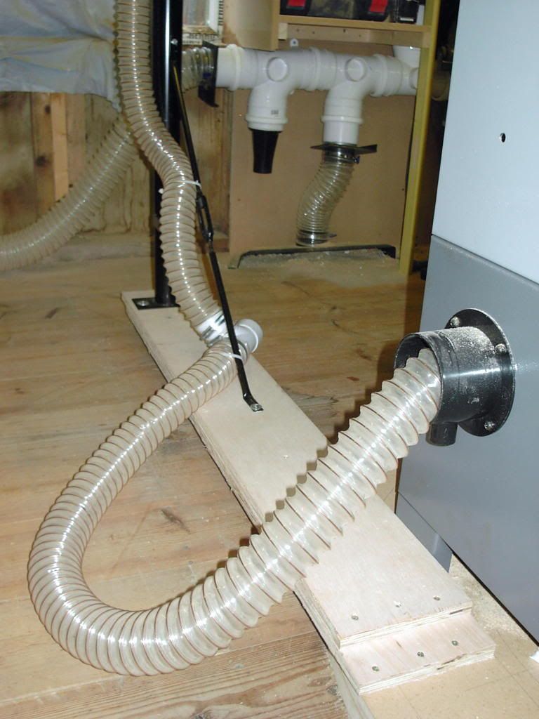
Photobucket One of the reasons it's taken some time to finish is now it's mounted on the turntable as seen opposite and is when I turn the saw I wanted the extraction to turn with it which it now does only a few minor things to finish to get it completed, things like a couple of fittings to reduce down from one pipe size to another size on the extraction, I order a couple of roller ball bearings as well, oh and apply a second coat of wax to the machine beds as well.

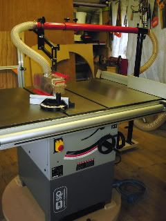
This photo show saw in its normal position facing across the workshop with overhead extraction

Photobucket Photo show saw turned 40 degrees to the right so if I want to cut a long length of timber open the workshop door and feed timber out through the opening


Photobucket This photo shows missing connection and the arm that supports the overhead extraction piping which is screwed to the turntable, directly under the stanchion poll I fixed an old chair caster (temp) two new roller balls bearings were ordered today to go under there so when turned it just swing round with the saw.

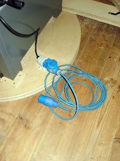
Photobucket This one showing electrics, plugs at both end, so I  can disconnect whichever end I like and it moves around with the turntable
Photobucket


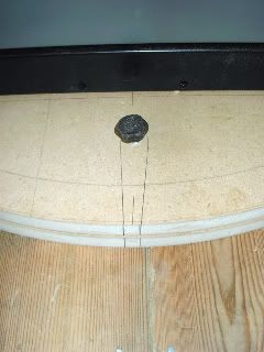
last photo showing locking bolt turntable now has been pre drilled degree holes all I need to do is pull the bolt and with one finger push and the saw glides around to where I want to position it.


Photobucket I know my life is much easier now with this turntable no more struggling to move the saw when it in the way just turn it in a jiff for that I have to thank Wellswood over on the UK who did a thread on his turntable.